TABLE OF CONTENTS
The settings can be accessed via the cog icon in the upper left corner.

1. General
Gerber Directory: The gerber directory sets the location which initially opens when selecting files during queue creation. If this is left blank, the Select File(s) button will open the directory from which files were most recently selected. The same will occur if the set gerber directory no longer exists. Change the directory by typing a new path or by clicking Browse.
Flip Data: Setting this to On will flip all loaded data across the Y-axis (X coordinates will flip from positive to negative and vice versa). Individual files can be flipped back using the queue adjustment feature described in section 3.2. Queue Adjustment.
Engineer Mode: Setting engineer mode to On will display additional information about the cut path within the plotter.
Laser COM Port: This setting should not be changed.
Door Bypass: Setting this to On allows cutting with the door open.
E-Stop Type: This setting should not be changed.
Fixture Home Type: This setting should not be changed without consulting Watt Laser engineers.
Enable Backstop Control: Setting this to Off removes the Enable Backstop button from the screen.
Disable Buzzer: When this setting is Off, the machine alarm will sound when the status light shows red (E-stop pressed).
X/Y Jog Speed: This sets the speed at which the X and Y axes move. This applies to all movement outside of operations such as cutting and marking.
Check For Update: Clicking this will check for an update. If one is available, the Update screen will display the changes and new features within the update and allow the update to be carried out. If the software is up to date, a message will appear stating this. Automatic update notifications will also be displayed. For more information on update notifications and updating the software, see the Checking For Updates article.
2. Cutting
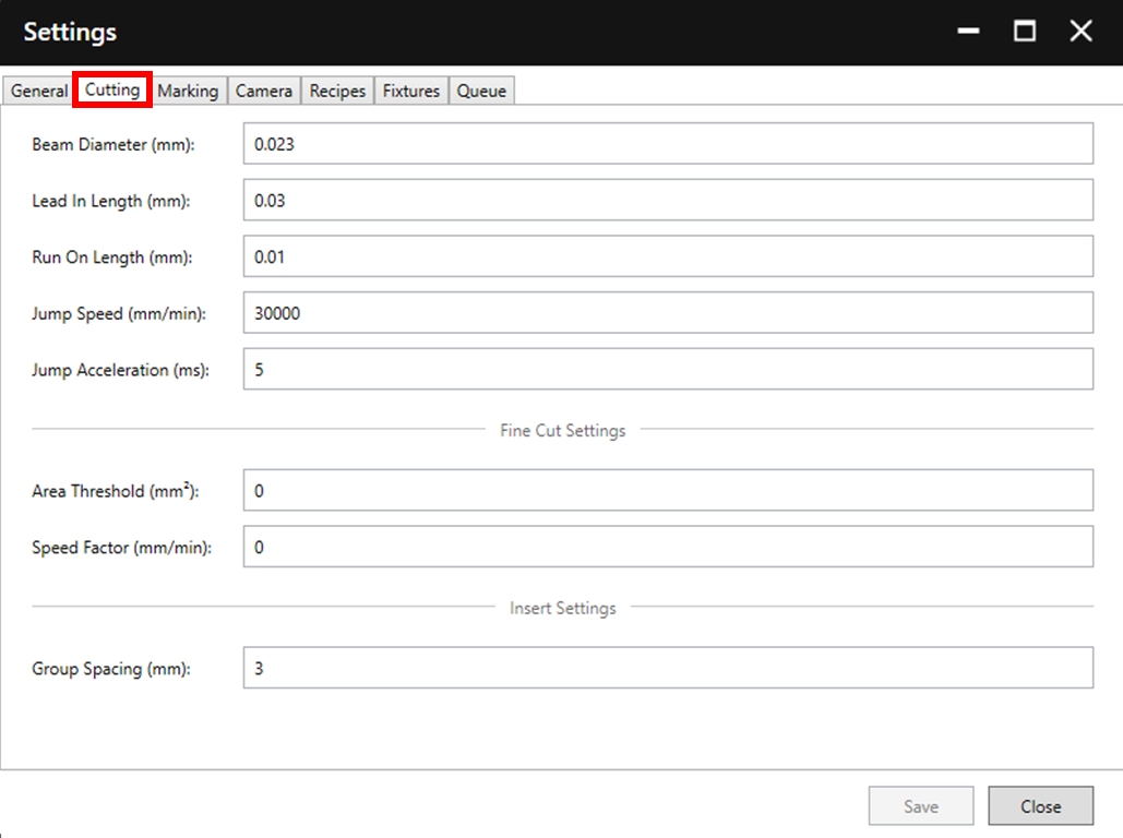
Beam Diameter: The beam diameter controls the size of the offset applied during cutting to achieve accurately sized apertures. If making a change to this value, ensure that the original value is noted.
Lead In Length: This value controls the distance travelled before the actual cutting path begins.

Run On Length: This value controls the extra distance cutting continues after completing a shape (the extra distance cut is along the same perimeter as the rest of the shape).
Jump Speed: This value controls the speed of movement between apertures.
Jump Acceleration: This value sets the time taken for acceleration when moving between apertures.
Area Threshold: This value sets the threshold value at which a slower cutting speed will be used. For more detail, see the Fine Cutting article.
Speed Factor: This value is multiplied by the cutting speed within each recipe to define the slower cutting speed used beneath the area threshold. For more detail, see the Fine Cutting article.
Group Spacing: This value sets the distance between shapes when grouping inserts (see section 3.2. Queue Adjustment).
3. Marking

Fill Type: The currently available fill types are Spiral, Concentric, and No Fill.
Fill Pitch: This value controls the space between the passes of the fill. A smaller pitch value will result in increased output time, a darker mark, and a more uniform appearance. A larger fill value will result in the opposite. This setting can be balanced by the power value set in the marking recipe used. See section 3.1.2. Recipe Details for more detail.

Fill Polygons: Setting this to On will allow polygon shapes to be filled.
4. Camera

Orientation: The orientation setting is used if it is necessary to invert the camera viewer in X or Y.
Thickness: This value sets the thickness of the crosshair shown in the camera view.
Colour: This sets the colour of the crosshair shown in the camera view.
Detection Settings: If changing these values, it is generally best to use the Detection Calibration tool. For more information on using this tool and understanding the parameters, see section 6.3. Camera Detection.
5. Plotter

The plotter settings can be used to set the colour with which each layer type is displayed in the plotter.
6. Recipes

The recipe tab is used to adjust the settings used for cutting and marking. Select the desired recipe for adjustment from the dropdown menu, or create, duplicate, or delete recipes using the three buttons right of the dropdown menu.
For more information on recipe parameters and adjusting/creating new recipes see section 3.1.2. Recipe Details.
7. Fixtures

Existing fixture sizes can be accessed through the dropdown menu, then adjusted, duplicated (copy symbol) or deleted (trash symbol). Alternatively, new fixture sizes can be created using the plus button.
Name: The name which will be displayed in the dropdown menu when selecting the fixture size during setup (see section 2.1. Loading a Stencil).
Width: This value sets the gap between the fixtures in the machine in millimetres. This does not need to be exact, a 736mm wide frame may require a value anywhere from 735-742mm for example.
To ensure an ideal width size, adjust the fixture width using the fixture jog buttons until well positioned (test with a frame). Then read the current fixture width and input this value into the appropriate fixture width setting.

Height: This value is not currently used.
8. Queue

See explanation in image. Reorder using the arrows on the left, delete or add items using the trash and plus icons on the right.