TABLE OF CONTENTS
1. Setup
1.1. Stencil Loading
Open the Watt Laser app and click Load/Unload to move to an easy position for loading the stencil.
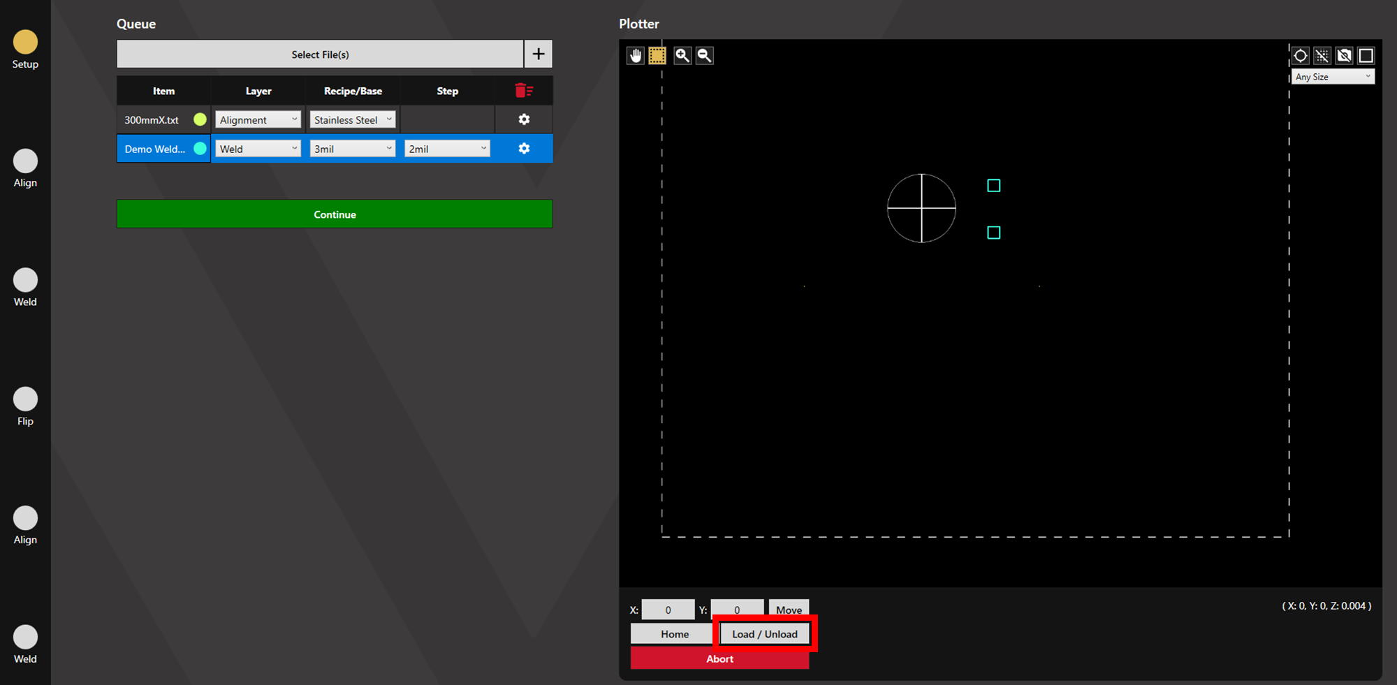
Place the stencil for on the machine such that the weld area lies on the vacuum plate. Turn the vacuum on and insert the step(s).
1.2. Loading Files
Select the desired files by clicking Select File(s) or by using drag and drop. For welding, an alignment file must be used. Set the layers to Alignment and Weld as appropriate.
For the alignment layer, choose the appropriate recipe for the desired Camera Lighting Settings and Detection Settings.
For the welding layer(s), select the appropriate Base folder followed by the appropriate Step for the desired Welding Settings.
1.3. Adjusting Data
Check that the plotter view matches the stencil for welding. The data may need flipped to match the stencil depending on which side is being welded first.
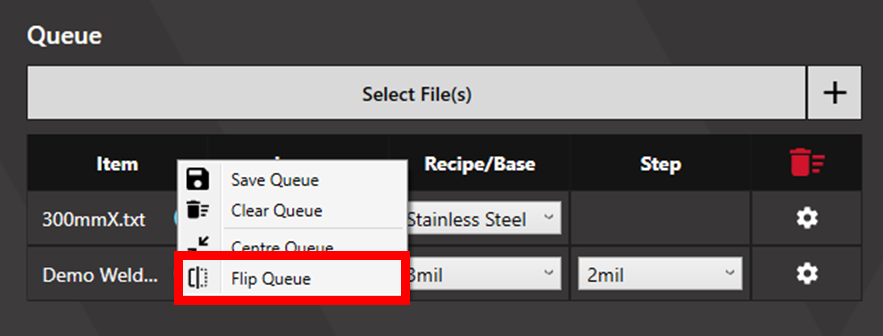
To flip for just one job, right-click the queue header to flip all layers (full queue flipping is recommended to ensure that alignment points match the weld locations).
Alternatively, to flip just one layer, right-click the layer and select Flip Data.
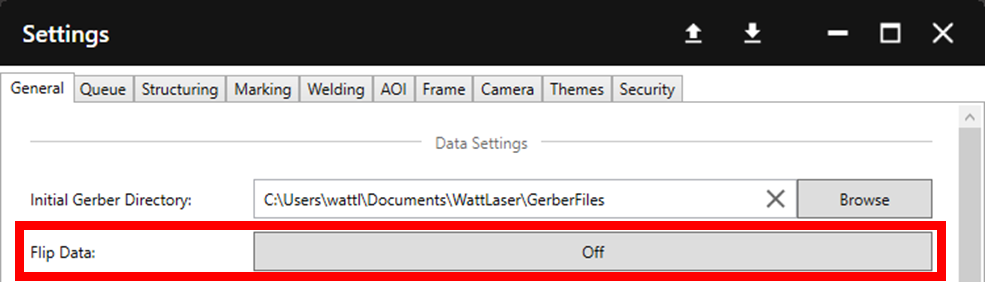
If it is found that data must always be flipped, data can be set to flip upon loading in Settings > General > Flip Data.
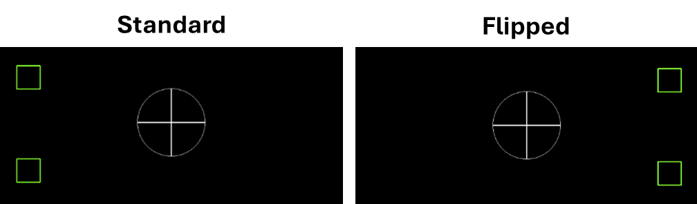
Flipping data inverts the X-coordinates to mirror across the Y-axis as shown below.
When the queue is correct and complete, click Continue to proceed to alignment.
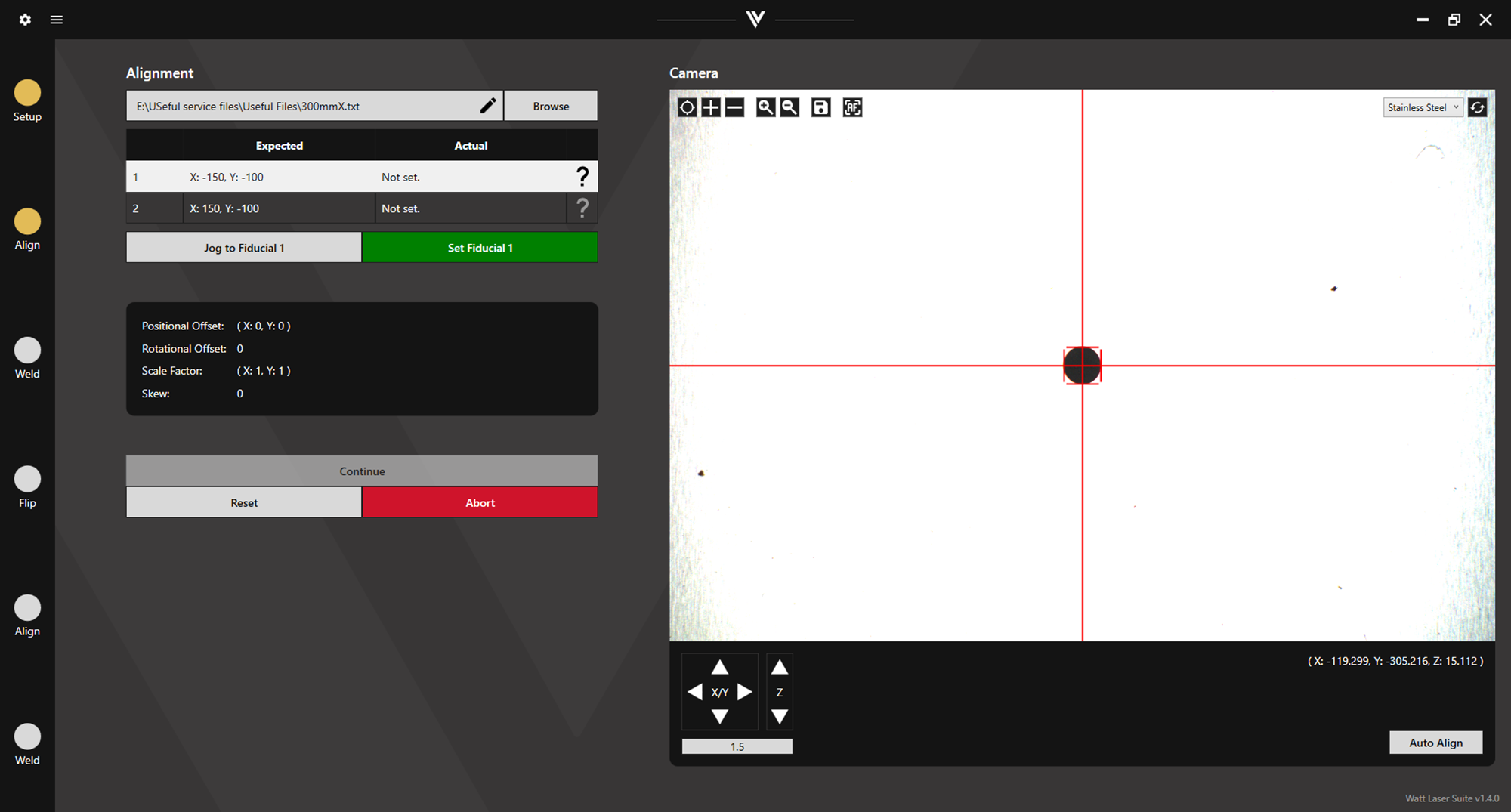
2. Alignment
2-4 points can be used for alignment. Four fiducial alignment is generally more accurate than 2 fiducial alignment but is not always necessary and takes more time.
If using an alignment file with more than 4 shapes, the shape selection window will prompt the operator to select 2-4 points for alignment. See the Alignment article for more information.
Click Jog to Fiducial to move to the expected fiducial locations. Align, then click Set Fiducial. Once all fiducials have been set, click Continue to proceed to welding.
3. Weld
Click preview to check that the weld locations are correct. If this seems wrong, refer to the troubleshooting points below.
If the preview appears correct, click Output to output all welds. Once welding is complete, click Continue to proceed.
Troubleshooting
If the preview does not appear to match the desired weld location, there are a variety of potential causes:
- Check that the stencil is oriented correctly. It may need rotated to match the data.
- If the weld preview appears to be flipped over the Y axis (X-coordinates are inverted), the data or the stencil may need flipped. Click on the Setup circle on the left of the screen, and refer to section 1.3. Adjusting Data.
- for instructions on flipping data. After flipping, realignment may be necessary.
3.1. Preview/Output Select Welds
To preview or output chosen welds only, click the pen icon.
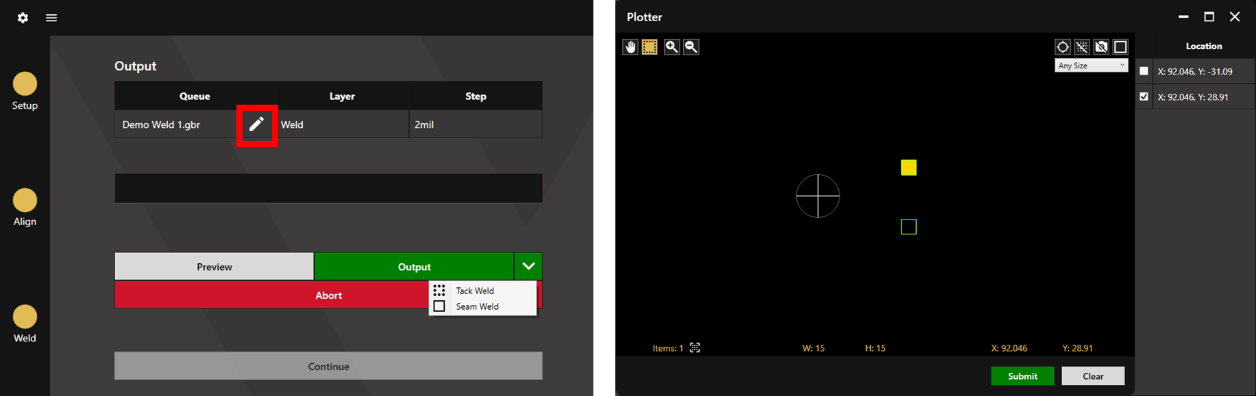
The number of shapes selected will be indicated in the queue.
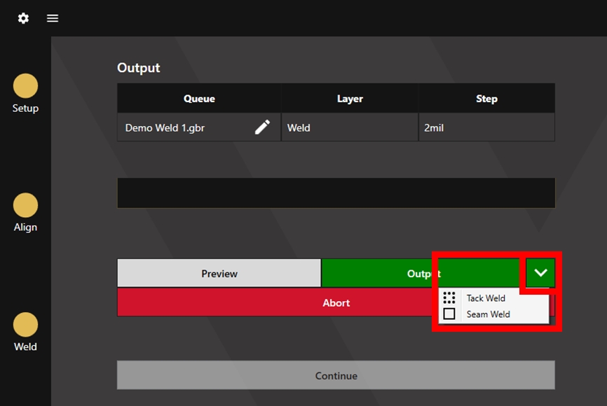
3.2. Alternative Weld Types
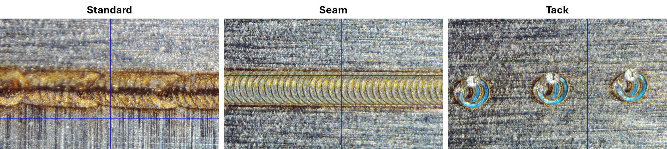
The standard output weld type is the recommended, optimised weld type. However, seam welds and tack welds can be chosen using the dropdown arrow next to the Output button.
See below for examples of each weld type (Note that these use different recipes so are not a direct comparison. The standard output image is also the only weld done on a real step and therefore the shadow of the step can be seen in only this image).
4. Flip
Once the first side welding is complete, the stencil needs flipped to weld the other side. The flip screen prompts this task.
If desired, a different recipe can be chosen for second side welding by clicking on the dropdown.
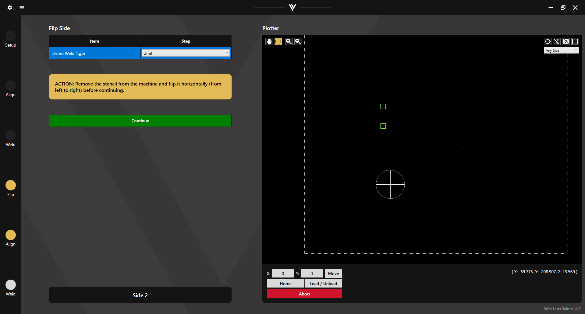
Once the stencil is flipped and the vacuum is on, click Continue to proceed to side 2 alignment.
5. Side 2 Alignment
As the stencil has been flipped, alignment must be conducted again. Refer to section 2. Alignment as the process is the same.
6. Side 2 Weld
Refer to section 3. Weld as the process is the same.
7. Weld Checks
A visual check can be done using the provided celestron microscope. Welds should generally look golden in colour. Not too light/shiny and not too burnt.
Check that no light can be seen through the weld. This is best done using a bright torch and/or in a dark room. Pin holes created by too much energy are usually to blame if light can be seen through the weld. Check the colour of the weld using the microscope and, if it looks burnt, reduce the power or increase the velocity. Alternatively, poor fit could be to blame (see below).
Check that the weld is strong. This can be done using a force gauge. A standard strength check looks to see that the weld can withstand >40N of force.
If either of these checks fail, there may be a problem with the welding recipe (for more detail see the Welding Recipes and Settings article) or with the insert fit. The fit can only be adjusted via the cutter. If using a Watt Laser SC12, refer to the Insert Layer section of the SC12 Process Manual.